Traffic engineering is one of the most interesting use cases for Segment Routing. Traffic engineering has been a hard and complex problem especially in large networks with multiple routing domains. In this post I’ll look into how SR traffic engineering addresses some of these issues as well as demonstrate them on Cisco IOS XR.
Traffic engineering
Traffic engineering (TE) is a mechanism for controlling path that the traffic takes through the network to the destination. On plain IP network, traffic is by default routed based on the IGP calculated best path. The path that the traffic takes can be influenced by changing metric values on individual links, but this affects all traffic transiting the link and can lead to unexpected results.
MPLS-TE enables establishment of LSPs that take specific path across the network. These paths can be specified manually or calculated dynamically based on constraints, such as available bandwidth, link attributes or path disjointness. Defining constraints on LSPs enable network operators to steer different types of traffic through different paths based on the traffic bandwidth/latency, redundancy or other business requirements.
RSVP has been traditional used as a control protocol for signaling the MPLS-TE LSPs. RSVP however has issues related to complexity of the protocol and scalability. Each node on the network has to maintain state for each LSP traversing through it. The LSP state also has to be periodically refreshed. This becomes a problem when the number of LSPs grows to thousands. Another issue with RSVP is that it doesn’t scale easily across IGP domains. End-to-end inter-domain LSP requires stitching or nesting of multiple tunnels. The configuration can also become complex.
SR traffic engineering
Segment Routing addresses multiple RSVP scalability problems. Unlike RSVP, SR doesn’t need to maintain state for LSPs in the transit routers. This is because the forwarding is based on the SID list on the individual packets. The head-end router just pushes the SID list to packets and the transit routers forward them according to the segment instructions. The state is held on the packets instead of devices.
Segment Routing can provide seamless multi-domain tunnels without complex LSP stitching or nesting. This requires that the head-end router that pushes the SID list to the packets has to have information about SIDs of other domains. Usually the SID information is provided by controller that has cross-domain view of the network.
Segment Routing has a special segment type called binding segment that can be used to abstract TE tunnel into SID value. Packets with binding SID will be steered into specific TE tunnel associated with it. This enables seamless integration of multiple inter-domain TE tunnels.
Configuring SR-TE
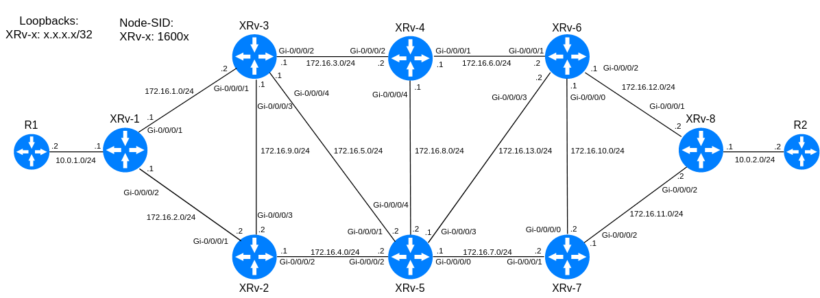
The example topology consist of eight XRv routers with IP addresses configured as seen in the figure below. R1 and R2 routers are used to test end-to-end connectivity.
I have have configured Segment Routing as in the Segment Routing Basic Configuration post, including prefix segments for loopback interfaces of the routers.
Traffic engineering has to enabled first on the IGP and global configuration on all the routers:
router isis 1
 address-family ipv4 unicast
  mpls traffic-eng level-2-only
  mpls traffic-eng router-id Loopback0
mpls traffic-eng
These commands enable IGP to advertise link attributes (eg. bandwidth, color) and populate the traffic engineering database (TED). Following command verifies presence of SR information on the TED:
RP/0/0/CPU0:XRv-2#show mpls traffic-eng topology segment-routing 1.1.1.1

IGP[0]:: IS-IS 1 level 2 , Strict SPF Disabled
Nodes:
  IGP Id: 0001.0001.1001.00, MPLS TE Id: 1.1.1.1

    Segment-Routing:
      TE Node-SID Index: 1
      SRGB Info: Start 16000, Size 8000

    Link[0]:Point-to-Point, Nbr IGP Id:0002.0002.2002.00, Nbr Node Id:2, gen:1269
      Frag Id:0, Intf Address:172.16.2.1, Intf Id:0
      Segment-Routing Adjacency-SIDs: 2
      Adjacency-SID[0]: 24001, Flags: V, L to Nbr:: IGP Id: 0002.0002.2002.00, MPLS TE Id: 2.2.2.2
      Adjacency-SID[1]: 24000, Flags: B, V, L to Nbr:: IGP Id: 0002.0002.2002.00, MPLS TE Id: 2.2.2.2
      Nbr Intf Address:172.16.2.2, Nbr Intf Id:0
      TE Metric:10, IGP Metric:10
      Ext Admin Group:
        Length: 256 bits
        Value : 0x::
      Attribute Names:
    Link[1]:Point-to-Point, Nbr IGP Id:0003.0003.3003.00, Nbr Node Id:3, gen:1270
      Frag Id:0, Intf Address:172.16.1.1, Intf Id:0
      Segment-Routing Adjacency-SIDs: 2
      Adjacency-SID[0]: 24003, Flags: V, L to Nbr:: IGP Id: 0003.0003.3003.00, MPLS TE Id: 3.3.3.3
      Adjacency-SID[1]: 24002, Flags: B, V, L to Nbr:: IGP Id: 0003.0003.3003.00, MPLS TE Id: 3.3.3.3
      Nbr Intf Address:172.16.1.2, Nbr Intf Id:0
      TE Metric:10, IGP Metric:10
      Ext Admin Group:
        Length: 256 bits
        Value : 0x::
      Attribute Names:
Prefixes:
 1.1.1.1/32,       SID index:         1, flags: N
   Adv. router(s)
   --------------
   0001.0001.1001.00
Next I will create simple dynamic SR LSP from XRv-1 (head-end) to XRv-8 (tail-end). Traffic engineering in IOS XR is configured using tunnel interface which represent the head-end of an LSP. All configuration regarding the tunnel is configured under the tunnel interface.
interface tunnel-te1
 ipv4 unnumbered Loopback0
 destination 8.8.8.8
 path-option 10 dynamic segment-routing
I created tunnel interface tunnel-te1 on the head-end router (XRv-1) with the destination of tail-end routers (XRv-8) router-id (typically loopback interface). IOS requires IP address on interface for forwarding, so I used address of the loopback. Path-option defines the tunnels path. In this example I used the dynamic option which creates LSP that follows the IGP calculated best path.
The show mpls traffic-eng tunnels shows information about the configured TE tunnels:
RP/0/0/CPU0:XRv-1#show mpls traffic-eng tunnels

Name: tunnel-te1  Destination: 8.8.8.8  Ifhandle:0xb0
  Signalled-Name: XRv-1_t1
  Status:
    Admin:    up Oper:   up   Path:  valid   Signalling: connected

    path option 10, (Segment-Routing) type dynamic  (Basis for Setup, path weight 40)
    G-PID: 0x0800 (derived from egress interface properties)
    Bandwidth Requested: 0 kbps  CT0
    Creation Time: Thu Dec 28 16:57:10 2017 (00:05:12 ago)
  Config Parameters:
    Bandwidth:        0 kbps (CT0) Priority:  7  7 Affinity: 0x0/0x0
    Metric Type: TE (global)
    Path Selection:
      Tiebreaker: Min-fill (default)
      Protection: any (default)
    Hop-limit: disabled
    Cost-limit: disabled
    Path-invalidation timeout: 10000 msec (default), Action: Tear (default)
    AutoRoute: disabled  LockDown: disabled   Policy class: not set
    Forward class: 0 (default)
    Forwarding-Adjacency: disabled
    Autoroute Destinations: 0
    Loadshare:          0 equal loadshares
    Auto-bw: disabled
    Path Protection: Not Enabled
    BFD Fast Detection: Disabled
    Reoptimization after affinity failure: Enabled
    SRLG discovery: Disabled
  History:
    Tunnel has been up for: 00:00:45 (since Thu Dec 28 17:01:07 UTC 2017)
    Current LSP:
      Uptime: 00:00:45 (since Thu Dec 28 17:01:07 UTC 2017)

  Segment-Routing Path Info (IS-IS 1 level-2)
    Segment0[Link]: 172.16.1.1 - 172.16.1.2, Label: 24003
    Segment1[Link]: 172.16.3.1 - 172.16.3.2, Label: 24005
    Segment2[Link]: 172.16.6.1 - 172.16.6.2, Label: 24001
    Segment3[Link]: 172.16.12.1 - 172.16.12.2, Label: 24007
The output shows that our tunnel is up. At the bottom of the output we can see the actual path that the tunnel takes. Since we specified the dynamic segment routing path option, the path uses IS-IS calculated best path to destination with adjacency-SIDs derived from the TED.
Now that the tunnel is set up, we still need to steer traffic into it. There are multiple ways to accomplish this but I’m going to use a simple static route pointing to the tunnel interface.
router static
 address-family ipv4 unicast
  10.0.2.0/24 tunnel-te1
The static route above configured on XRv-1 steers traffic destined for XRv-8 - R2 network through the TE tunnel. To verify that our tunnel is working, I will run traceroute from R1 to R2.
R1#traceroute 10.0.2.2

Type escape sequence to abort.
Tracing the route to 10.0.2.2

  1 10.0.1.1 64 msec 60 msec 76 msec
  2 172.16.1.2 [MPLS: Labels 24003/24001/24003 Exp 0] 124 msec 64 msec 60 msec
  3 172.16.3.2 [MPLS: Labels 24001/24003 Exp 0] 64 msec 60 msec 60 msec
  4 172.16.6.2 [MPLS: Label 24003 Exp 0] 36 msec 44 msec 64 msec
  5 172.16.12.2 68 msec 60 msec 60 msec
  6 10.0.2.2 64 msec 20 msec 20 msec
Because TE tunnels are unidirectional, we would also have to create tunnel in reverse direction for the return traffic to be forwarded over the LSP.
Explicit path
The the dynamic path used in the previous example doesn’t take advantage of the power of TE since it only follows the normal IGP best path. The explicit path option gives us complete control of the traffic path.
I will create explicit path so that the traffic will take the lower path (XRv-2-5-7) to XRv-8. I use the node-SIDs here, but adjacency-SIDs could be used as well for more granular control.
explicit-path name XR2-5-7
 index 1 next-label 16002
 index 2 next-label 16005
 index 3 next-label 16007
 index 4 next-label 16008

interface tunnel-te1
 path-option 10 explicit name XR2-5-7 segment-routing
The new path is again verified by traceroute from R1. Note that the index 1 label is not shown on the traceroute because of PHP.
R1#traceroute 10.0.2.2

Type escape sequence to abort.
Tracing the route to 10.0.2.2

  1 10.0.1.1 36 msec 60 msec 24 msec
  2 172.16.2.2 [MPLS: Labels 16005/16007/16008 Exp 0] 12 msec 8 msec 8 msec
  3 172.16.4.2 [MPLS: Labels 16007/16008 Exp 0] 20 msec 8 msec 4 msec
  4 172.16.7.2 [MPLS: Label 16008 Exp 0] 16 msec 4 msec 12 msec
  5 172.16.11.2 4 msec 12 msec 4 msec
  6 10.0.2.2 20 msec 20 msec 16 msec
Inter-domain TE tunnels with binding segment
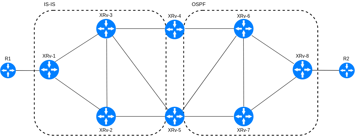
To illustrate the use case for SR binding segment, I divided the previous network into two separate routing domains with one running OSPF and the other IS-IS.
First we need to create tunnel from the domain border router XRv-4 to destination router XRv-8:
explicit-path name XR-8
 index 1 next-label 16008
!
interface tunnel-te1
 ipv4 unnumbered Loopback0
 destination 8.8.8.8
 binding-sid mpls label 4000
 path-option 10 explicit name XR-8 segment-routing
The IOS XR automatically assigns bindig-SID for SR-TE tunnels, but you can also define it manually like I did above. The binding-SID can be verified from the tunnel details:
RP/0/0/CPU0:XRv-4#show mpls traffic-eng tunnels name tunnel-te1 detail

Name: tunnel-te1  Destination: 8.8.8.8  Ifhandle:0x90
  ...
  Binding SID: 4000
Next we change the explicit path on XRv-1:
explicit-path name interndomain
 index 1 next-label 16003
 index 2 next-label 16004
 index 3 next-label 4000
!
interface tunnel-te1
 path-option 10 explicit name inter-domain segment-routing
Note that we refer to the binding-SID on the explicit-path. Let’s see what the traceroute from R1 shows us now:
R1#traceroute 10.0.2.2

Type escape sequence to abort.
Tracing the route to 10.0.2.2

  1 10.0.1.1 92 msec 88 msec 100 msec
  2 172.16.1.2 [MPLS: Labels 16004/4000 Exp 0] 84 msec 84 msec 84 msec
  3 172.16.3.2 [MPLS: Label 4000 Exp 0] 80 msec 84 msec 80 msec
  4 172.16.6.2 [MPLS: Label 16008 Exp 0] 64 msec 60 msec 60 msec
  5 172.16.12.2 60 msec 64 msec 60 msec
  6 10.0.2.2 96 msec 88 msec 88 msec
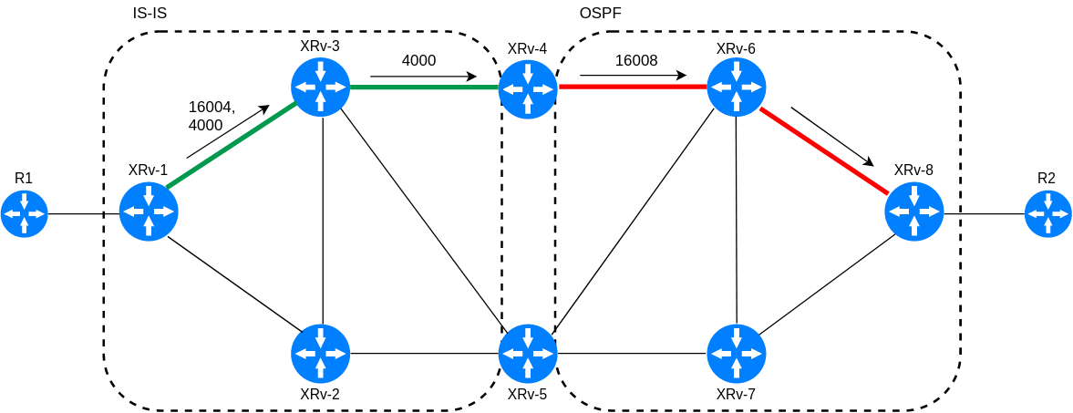
When traffic reaches XRv-4 with the label of the binding-SID, it forwards the traffic to the associated TE tunnel and pushes the label stack. This is illustrated in the figure below.
The binding segment seamlessly stitches the two tunnel together. It acts as abstraction point hiding the internal topology and changes from outside. Binding segment can also help reduce depth of the label stack that the head-end has to push.
Summary
Traffic engineering is a broad topic and I only scratched a surface here. SR-TE is still a new concept but it looks to provide most of the same features as traditional RSVP based TE with more simple and scalable manner. Although you can create SR-TE tunnels manually as I demonstrated, a more scalable solution is to use central controller (PCE) to calculate the LSPs and program the tunnels on the routers. I will cover this on a future post.


